
Building Tips
Unique Drive Trains

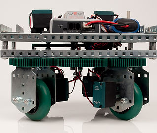
This design is also referred to as a "Skid Steer Drive", it is a very common type of drive train in robotics. The wheels on the left and right side of the drive are locked in place and powered by separate motors. Steering this drive train is accomplished by varying speeds on the right and left side. It is capable of a zero-radius turn; one side would be powered forward and the other, backward.
Tank Drive

The X-drive is a type of drive train design which is able to strafe in all four directions. The base consists of four omni-wheels, placed at 45 degrees relative to each other. This drive is much harder to program and control. For instance, each wheel is given a directional vector, the right front wheel and the left back wheel are at a 135 degree angle, both motors are programmed to move forward. The right back wheel and the left front wheel, both are at 45 degrees and moving forward. All of the vectors cancel and allow the robot to move forward.
X-Drive

The H-drive is also known as a "5 omni-directional wheel drive" which allows the robot to maneuver in many different directions compared to a standard tank drive. The middle omni-directional wheel allows the robot to strafe. This design requires 5 motors; two on each side of the robot and one for the center.
H-Drive
Another type of drive train in this competition is known as swerve drive. A swerve drive is a chassis when the wheels is not only powered to move forwards or backwards, but has the ability to steer independently too.
Swerve Drive
Unique Lift Design

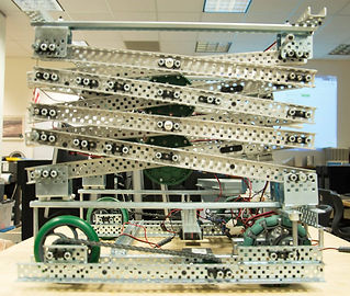
The 6 bar gets its name for the same reason the 4-bar got its name, and that is because it uses 6 bars to achieve lift. To build an effective 6 Bar Lift, the spacing is very critical as the lengths of certain bars need to be the same as others and the pivot points symmetrical.
6 Bar Lift

The chain lift works similarly to a 4-bar and 6-bar linkage as the bar attached to it will always remain stationary throughout the movement of the arm.
Chain Lift

A four bar lift system utilizes 4 separate bars to present a great lifting mechanism. The main reason why 4 bar lifts are used is to distribute the weight and always remain parallel to the fixed link which is the part with the gear, as the c-channel will always rotate around this point.
4 Bar Lift
A scissor lift allows the robot to reach high places as a series of two c-channels attached together at the center called stages. The stages are attached and stacked upon each other. However, they are very unstable and one of the harder lifts to build.